
EV Battery Pack and Thermal Interconnect Optimization
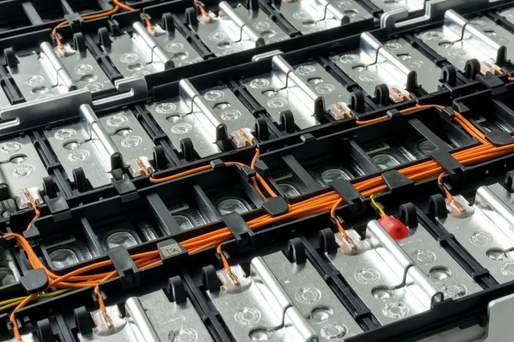
Design busbars and interconnects to carry both continuous and peak current without excess Joule heating. In 400V and 800V architectures, low-resistance, low-inductance paths help stabilize power delivery and reduce hot spots during fast charge events.
Core Design Priorities
- Cross-sectional sizing: Match conductor area to the full current load, not just nominal operation, to control temperature rise under peak demand.
- Transient behavior: Factor in skin effect and current crowding in high-frequency switching and transient modes.
- Material choice: Select high-conductivity copper or aluminum alloys based on resistance targets, mass limits, and joining method compatibility.
- Cooling integration: Align interconnect layout with liquid cooling channels so the pack holds a tight thermal spread.
- Fast-charging support: Dimension the electrical path for 4C fast charging and short charging windows, including SOC 30% to 80% in about 10 to 15 minutes.
- Thermal balance: Keep thermal deltas low across the pack to support stable performance and long-term reliability.
Practical Outcome
A well-designed busbar network reduces resistive loss, improves thermal control, and supports high-voltage charging without compromising pack efficiency.
EV Battery Pack Busbar and Interconnect Design Best Practices: Mechanical Durability
Vibration and Fatigue Control
I design busbars and interconnects to hold up under real vehicle motion, not just bench tests. The main failure points are weld fatigue, clamp loosening, and crack growth from repeated vibration.
- Use expansion loops to absorb movement from chassis shake and pack deformation.
- Add flexible laminated sections where rigid copper would otherwise concentrate stress.
- Keep bend radii stable so the busbar does not harden at the fold line.
- Spread load across the joint area to reduce local fatigue in long-term operation.
Stress and Sealing
Multi-axial stress shows up when vibration, heat rise, and enclosure pressure all hit at once. I treat sealing and mechanics as one system, because a strong joint still fails if moisture, dust, or thermal cycling breaks the stack.
- Match Coefficient of Thermal Expansion (CTE) between busbar, insulator, and terminal stack.
- Use insulation systems that stay stable under thermal surge and repeated expansion.
- Maintain high-voltage isolation clearance and creepage under deformation.
- Build for IPX9K waterproof validation so sealing stays intact under harsh wash and road exposure.
Practical Durability Targets
| Risk | Best practice | Result |
|---|---|---|
| Vibration fatigue | Expansion loops, flexible laminated busbars | Lower crack risk |
| Thermal cycling | CTE-matched materials and stack design | Better joint stability |
| Water ingress | Reinforced sealing and enclosure interfaces | Stronger environmental protection |
| HV safety loss | Controlled insulation spacing | Safer operation |
What I Prioritize
- Multi-axial stress resistance for long service life.
- Thermomechanical integrity across hot and cold cycles.
- Dissimilar material control when copper, aluminum, and plated interfaces meet.
- Durability under vibration without giving up low-resistance current flow.
For global EV use, I keep the design conservative on isolation, sealing, and fatigue margin, because a busbar has to survive the road, the climate, and the full pack lifecycle.
Structural Integration in Next-Gen Pack Architectures
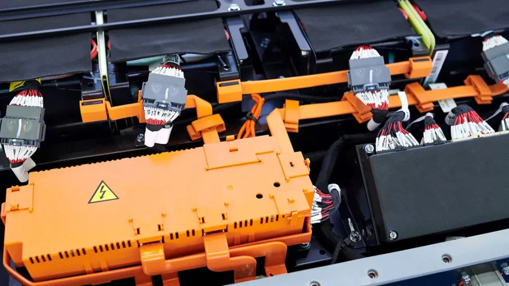
Cell-to-Chassis (CTC) interconnect topology is transforming EV battery pack design by replacing traditional modular grid systems with direct, integrated connections. This approach reduces weight, simplifies assembly, and cuts BOM costs—up to 20% savings compared to legacy designs. The LEAPENERGY Gen3 CTC 2.0 framework exemplifies this, combining high-current capacity with optimized signal and sensing routing within busbar structures.
Integrating signal pathways directly into busbars minimizes EMI, ensuring BMS accuracy and reliability. This design also supports high-voltage architectures like 800V systems, enabling faster charging and improved thermal management. The result is a more compact, efficient, and durable pack that withstands harsh environments and long-term operation.
By adopting CTC topologies, manufacturers can achieve significant efficiency gains—reducing component count and weight while enhancing safety and performance. This aligns with the industry’s move toward simplified, high-performance battery pack architectures that meet global safety standards and deliver reliable energy storage solutions.
Advanced Joining for Busbars
I keep the joint design simple: low resistance, stable metallurgy, and repeatable production.
Welding choices
- I use automated laser beam welding (LBW) when I need tight control, high throughput, and consistent joint geometry in busbar production.
- I use ultrasonic welding for thinner conductors and sensitive assemblies where lower heat input helps reduce distortion.
- For high-volume EV battery pack busbar and interconnect design best practices, the process has to match the metal stack, joint size, and current load.
Al-Cu joint control
- In dissimilar metal joining (Al to Cu), I control Intermetallic Compound (IMC) layer formation closely because thick IMC layers raise resistance and make joints brittle.
- I keep the interface clean and stable to reduce porosity and limit weak spots in multi-layer laminated busbars.
- I treat Coefficient of Thermal Expansion (CTE) mismatch as a real design risk, not a secondary detail.
Mechanical retention
- I use bolted interfaces where serviceability matters, but I lock down torque control to avoid loosening and local heating.
- I combine welds and mechanical retention when the pack needs both electrical continuity and vibration resistance.
- For long-life packs, I design joints to handle continuous vs peak current carrying capacity without drift in contact resistance.
Surface and corrosion protection
- I specify surface platings to improve corrosion resistance and support stable performance in humid and harsh environments.
- I protect copper and aluminum interfaces early, because surface degradation can weaken low inductance interconnect topology and raise loss.
- For global applications, I keep the joint stack aligned with UL 2580 battery safety compliance and ISO 26262 functional safety framework expectations.
Global Safety Compliance & Automated Quality Control
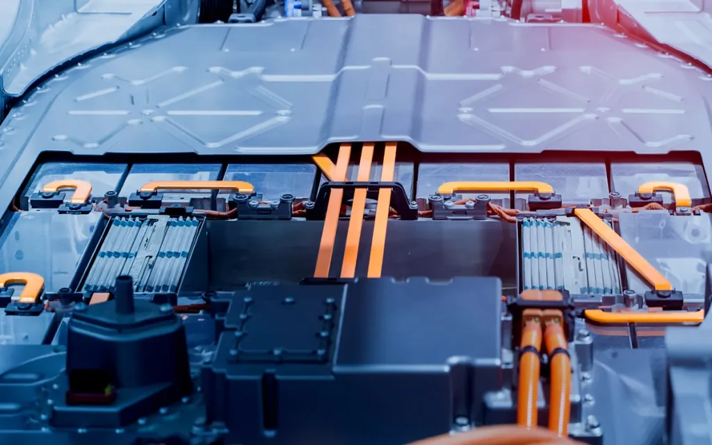
Ensuring global safety compliance in EV battery pack busbar and interconnect design requires rigorous material selection and manufacturing controls. Insulation materials must withstand thermal surges to prevent breakdowns during high-current events, aligning with safety standards like UL 2580 for battery safety and ISO 26262 for functional safety. Proper insulation not only enhances thermal surge endurance but also reduces risks of thermal runaway propagation, which can lead to catastrophic failures.
Achieving high-voltage safety standards, such as IP2X finger safety ratings and waterproof validation like IPX9K, demands precise design and assembly practices. Incorporating automated inline inspection and non-destructive testing (NDT) techniques ensures consistent quality, verifying joint integrity, weld quality, and insulation effectiveness at every production stage. These advanced quality control methods help prevent defects that could compromise safety or longevity.
Manufacturing tolerances must be strictly controlled to meet international standards. This includes tight dimensional control for busbar and interconnect components, especially in dissimilar metal joining (e.g., aluminum to copper), where intermetallic compound (IMC) layer formation can impact joint reliability. Automated laser beam welding (LBW) and torque-controlled bolted interfaces are key to maintaining consistency, durability, and compliance across high-volume production runs.
By integrating these safety and quality practices, manufacturers can deliver reliable, high-performance EV battery packs that meet global standards, minimizing risks and ensuring long-term operational safety.
 English
  German
  Chinese
  Spanish